What is a membrane switch?
A membrane switch is a thin switching interface that uses flexible layers and conductive contacts to register a press. In a normally open design, pressure makes an upper conductive element touch the lower contacts, closing the circuit and sending a signal to the connected electronics.
Membrane switches combine several input locations in a compact, flexible structure, which is why they appear on equipment, appliances and electronic devices. Monobee prints custom switch layouts directly from digital designs.
From a digital design to a printed interface circuit
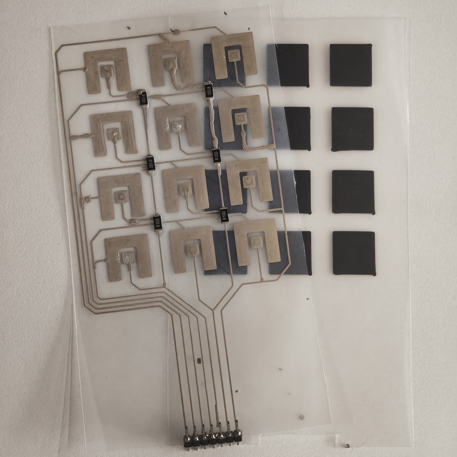
This study shows how the conductive layers of a membrane switch can be fabricated straight from digital files. The prototype has twelve switch contact geometries, fine silver routing and a common connector on one PET sheet, with matching carbon pads on a second.
It is a prototyping and circuit fabrication example, not a validated switching performance study.
How a membrane switch works
In this prototype the switch is built from two printed PET sheets. The lower sheet carries open silver contacts for each key, and the upper sheet carries a carbon pad above each one. Pressing a key brings the carbon pad down onto its silver contacts and closes the circuit.
The schematics below are conceptual and not to scale.
- PET film (two sheets)
- Printed carbon pad, upper sheet
- Printed silver contacts, lower sheet
Two printed PET sheets, nothing in between.
One PET sheet carries the silver circuit: open contact geometries for each key, routed traces and a common connector. The second PET sheet carries a matching grid of carbon pads. Laid face to face, each carbon pad sits over its silver contact and closes it when pressed. No separate spacer layer is used.
Silver and carbon BeeInk on two PET sheets
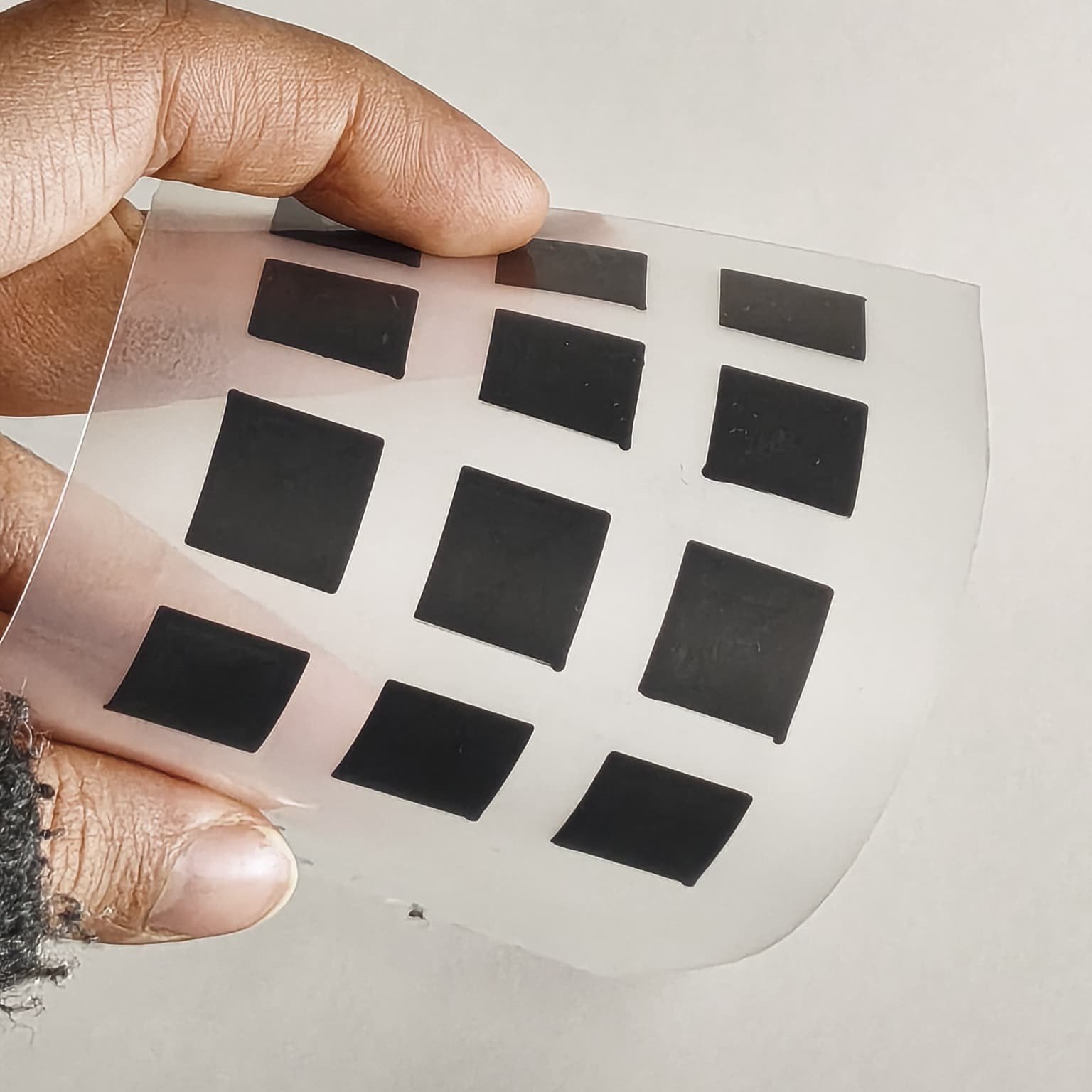
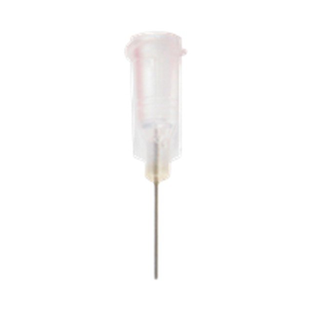
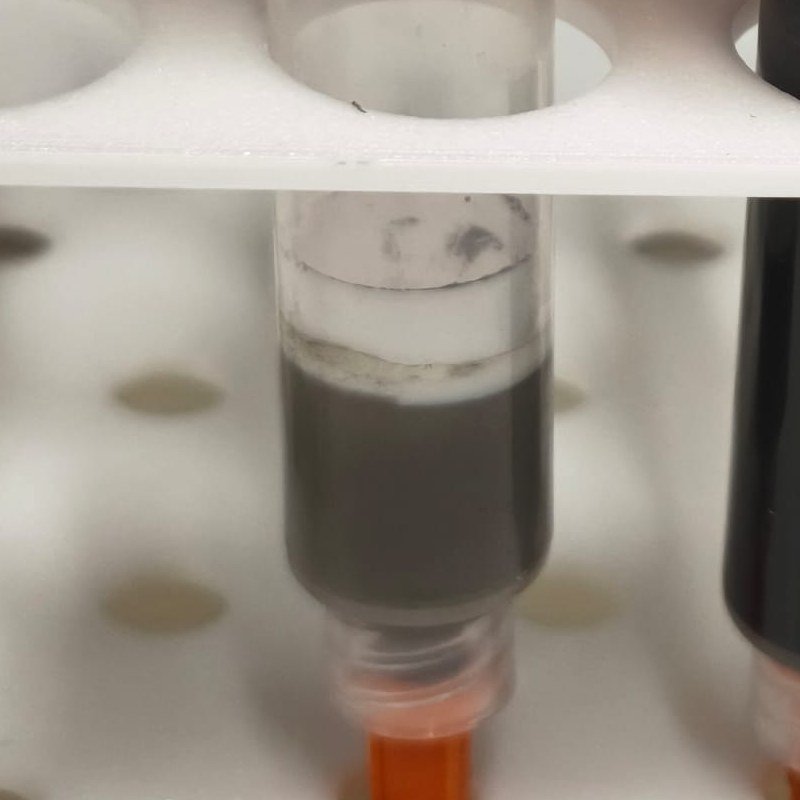
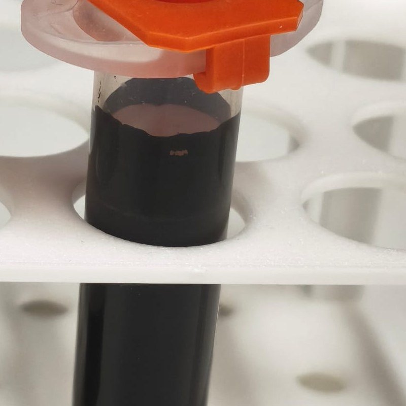
Silver BeeInk forms the conductive circuit that connects each switch region to the external electronics. Carbon BeeInk forms the contact pads on a second sheet. Both were printed with a 27G metal syringe tip (0.21 mm inner diameter).
| LAYER | MATERIAL | FUNCTION |
|---|---|---|
| Circuit sheet | Silver BeeInk on PET | Switch contacts, routed traces and connector lines |
| Contact sheet | Carbon BeeInk on PET | Pads that bridge the silver contacts when pressed |
| Substrate | PET film, two sheets | Flexible support for each printed layer |
Fabrication workflow
- 01Design both layers: silver contacts, routing and connector on one, matching carbon pads on the other.
- 02Print the silver circuit on the first PET sheet with Silver BeeInk.
- 03Print the carbon pads on the second PET sheet with Carbon BeeInk.
- 04Cure each sheet, then inspect continuity, adhesion and unintended shorts.
- 05Lay the sheets face to face so each carbon pad sits over its silver contact.
- 06Evaluate switching behavior, contact resistance, actuation response and durability as needed.
Choosing materials
Material selection follows the target device: architecture, flexibility, contact behavior, electrical resistance, environmental exposure and manufacturing constraints.
Because each layer comes straight from a digital file, no dedicated printing screen is prepared, which makes revisions and low-volume prototypes practical.
Consumables
How can researchers evaluate a membrane switch circuit?
Electrical, mechanical and environmental checks together describe how the interface will behave.
No switching performance values are reported for this prototype. Contact resistance, actuation force, repeated-use behavior and environmental stability should be verified experimentally for the intended design.
Potential research applications
Printed membrane switch circuits can be explored across several product areas.
- Industrial interfacesOperator panels, instrumentation controls and compact human-machine interfaces.
- Medical and laboratory equipmentCustomized low-profile control panels, subject to the validation needs of the final device.
- Consumer electronics and appliancesCustom button layouts and conductive patterns for thin interface assemblies.
- Flexible electronics researchConductive routing, switch geometry and multilayer flexible circuit concepts on polymer films.
These are potential application directions for printed membrane switch circuits rather than demonstrated end uses of the prototype shown.
The interface begins with the printed circuit.
A membrane switch combines electrical design with mechanical interaction. Conductive geometry sets how the switch regions connect, while spacer structure, contact arrangement and substrate flexibility shape the response to pressure.
Direct Ink Writing makes these layouts practical to prototype in-house. Iterating digitally, faster and more cost-efficiently, lets developers test new interface concepts before committing to a final assembly or production method.
From conductive patterns to interactive electronics.
Monobee printed a silver circuit layer and a carbon contact layer on two PET sheets, which together form a working membrane switch concept. It is a practical route to customized interface circuits.
The next step is application specific: verify switching behavior and validate electrical and mechanical performance under relevant conditions.
RELATED MATERIALS: SILVER AND CARBON BEEINK →A membrane switch relies on thin flexible layers and conductive contacts that meet under pressure. A mechanical switch uses a dedicated mechanical contact assembly to create the signal.