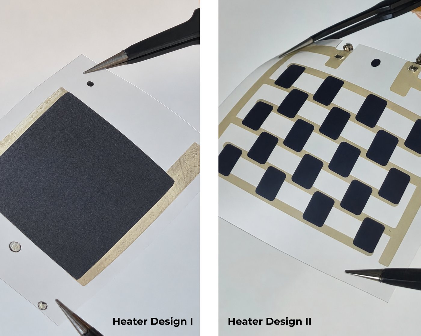

HEATER 1 · UNIFORM HEATING
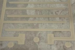
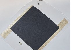
Printed silver conductive regions with a large carbon heating area, designed to distribute heat across a broader surface.
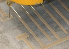
Using Beespenser's Monobee microdispensing platform, two flexible heater architectures were fabricated on 125 µm PET using silver and carbon conductive inks. Multilayer printing and fiducial-assisted alignment enabled different conductive materials to be integrated within the same device while maintaining controlled layer positioning.
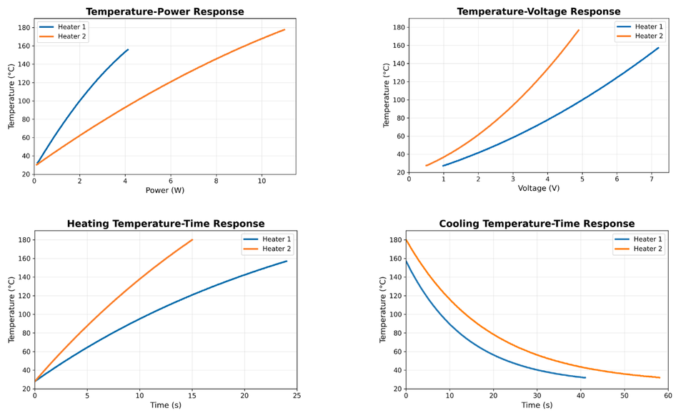
By changing the heater geometry, the two designs demonstrated distinctly different thermal behavior: one produced a more uniform temperature distribution, while the other delivered faster, localized heating and reached temperatures up to 180 °C.
Flexible heaters are used wherever heat needs to be delivered through a thin, lightweight or conformable surface. Their thermal behavior is strongly influenced by material properties, electrical resistance and heater geometry.
In this case study, we explored how Monobee can be used to fabricate multilayer flexible heaters combining silver and carbon conductive inks on PET, and how different printed geometries influence heating speed, maximum temperature and heat distribution.
The objective was not only to fabricate a working heater, but also to demonstrate how researchers and R&D teams can rapidly iterate between heater architectures without relying on externally fabricated heating elements for every design cycle.
Two heater geometries were designed and evaluated. Both structures combine a silver conductive layer with a carbon resistive heating layer, but use different geometries to shape the thermal response.
Printed silver conductive regions with a large carbon heating area, designed to distribute heat across a broader surface.
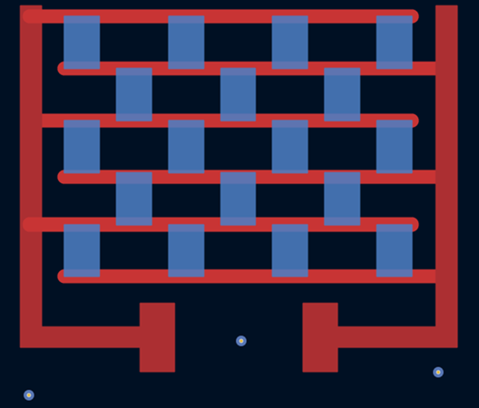
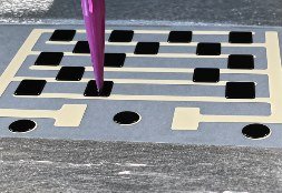
An alternative silver-carbon pattern with multiple distributed conductive features throughout the heating area.
The first functional layer was printed and thermally cured. Circular fiducial markers were then used for multilayer positioning before the second material was dispensed and the final cure completed. This workflow integrated the two functional materials within the same flexible device.
| PARAMETER | SILVER INK | CARBON INK |
|---|---|---|
| Substrate | PET, 125 µm | PET, 125 µm |
| Tip inner diameter | 0.25 mm | 0.41 mm |
| Printing speed | 50 mm/min | 50 mm/min |
| Extrusion multiplier | 10 | 95 |
| Z-height / Z-gap | 0.02 mm | 0.02 ± 0.02 mm |
| Curing | 90–140 °C / 10 min | 90–120 °C / 5 min |
| Fiducial markers | Circular, at least 3 | Circular, at least 3 |
Changing the printed architecture resulted in a clear difference in electrical and thermal performance. Geometry shifted the balance between heating rate, maximum temperature and temperature distribution.
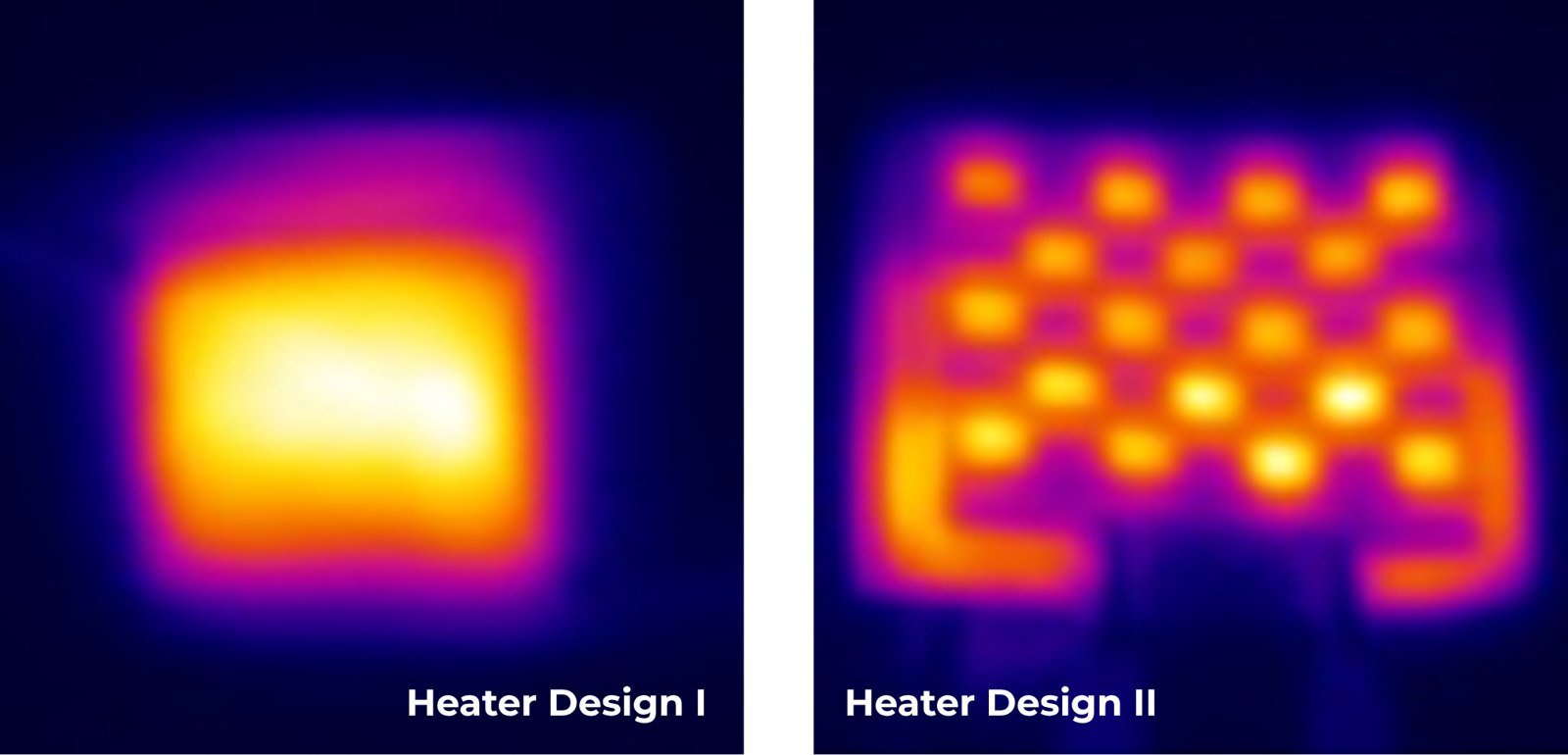
Reached 157 °C in 24 seconds. Thermal imaging showed a broad, comparatively uniform heated region, suited to applications where temperature needs to be distributed across a larger surface.
Reached 180 °C in 15 seconds. Its thermal response was more spatially concentrated, showing how printed geometry can shift a device toward higher-temperature, localized heating.
Power, voltage and time-based measurements reveal how each heater architecture responds under different operating conditions.
The heater itself becomes a design variable. A new geometry can be printed, tested and compared in-house, within the same development loop.
Using the same fabrication platform and substrate, the two printed architectures produced significantly different maximum temperatures, heating rates and thermal distributions. Heater designs can be iterated according to the application's priority: uniform heating, localized heating, response time, operating temperature or electrical resistance.
Conventional heater development can require externally manufactured elements or processes optimized around a fixed geometry. With printed functional materials, the heater can be redesigned together with the electronic system and adapted to the available surface, substrate and thermal requirement.
With an in-house microdispensing workflow, researchers can move from a new heater geometry to a physical prototype without conventional tooling or external fabrication for every iteration.
Printed flexible heater architectures can be adapted to the required substrate, heated area, temperature range and thermal distribution.
The results above show one PET-based implementation using silver and carbon conductive inks. Final material, geometry and process parameters should be selected according to the target application.
There is no single ideal flexible heater architecture. A wearable heating element, a battery thermal-management component and a localized microfluidic heater can require very different temperature profiles. Two silver-carbon architectures printed on the same PET substrate produced clearly different resistance, heating rates, maximum temperatures and thermal distributions.
RELATED MATERIALS: SILVER AND CARBON INKS →Yes. In this case study, silver and carbon functional inks were deposited as separate layers, with fiducial markers used to support positioning between printing steps.